So here it is, the depths of winter, time to get working on a long-neglected farm 2.0 project: the chicken coop controller.
The thing about having free-range chickens is that they need to be let out every morning and shut-in every evening. That’s a minor inconvenience when your chicken coop is a few hundred feet from your front door, but if you’re contemplating an eggmobile it becomes a much bigger hassle.
Luckily this is the 21st century, and we have the technology to automate this particular task. Sure, you can go out and buy an off-the shelf chicken coop door opener/closer, but where’s the fun in that? Plus, it doesn’t really stick to our criteria: cheap, open source, adaptable, green, and labor-saving.
So here we go.
Off to build our own chicken coop controller.
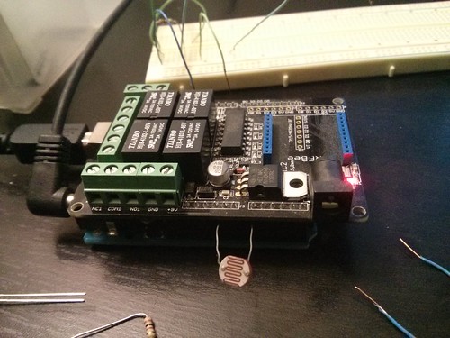
I’ve started with the gold standard of open-source DIY programmable controllers, the Arduino. The Arduino is basically a tiny $30 computer with a bunch of different inputs and outputs. It’s a blank silicon slate that, with a little programming, can be made to do just about anything. Programming anything other than a TI-85 calculator is new to me, so I keep my copy of Simon Monk’s Programming Arduino: getting started with sketches close by.
To do some specific tasks the Arduino needs a bit of help. Most of the time you just need a few simple electronic bits like sensors, resistors, switches and the like, but occasionally you need a bit more help.
I’m planning on opening a chicken coop door with an electric motor which the Arduino can’t handle on it’s own (and I’m not smart enough to figure out how to control a motor with a lone transistor) so I chose the Seeed studio relay shield to help the Arduino out.
After an afternoon of re-learning all the Arduino programming I forgot in the past year or two, I managed to cobble together a little bit of code to get the chicken coop controller off the ground.
With (so far) only a single photocell, the controller can cycle one of it’s relays when it gets dark out. In it’s current state the relay is activated about 30 minutes after sunset, with a 30-second rolling average to keep transient shadows, dark clouds, etc. from triggering the “door” to close.
Phase two will involve actually adding a motor, high & low limit switches, and an indicator light (or two) and all the associated programming. Maybe by that point I’ll be able to do more than a couple hours of tinkering with the Arduino before my head hurts…
And for anyone who’s interested, here’s the code so far:
#include <movingAvg.h> //https://github.com/JChristensen/movingAvg
#define PHOTOCELL_PIN A0                 //connect photocell from A0 pin to ground
 movingAvg photoCell;                     //declare the moving average object
 int pc;                                  //a single photocell reading
 int avg;                                 //the moving average
 const byte Relay1 = 7;                   //define digital pin 7 as operating relay
 const byte Relay2 = 6;                   //define digital pin 6 as operating relay
 const byte Relay3 = 5;                   //define digital pin 6 as operating relay
 const byte Relay4 = 4;                   //define digital pin 4 as operating relay
void setup(void)
 {
 digitalWrite(PHOTOCELL_PIN, HIGH);    //turn on pullup resistor
 Serial.begin(9600);                   //begin serial output
pinMode(Relay1, OUTPUT);              //set relay pins as output
 pinMode(Relay2, OUTPUT);
 pinMode(Relay3, OUTPUT);
 pinMode(Relay4, OUTPUT);
 }
void loop(void)
 {
 pc = analogRead(PHOTOCELL_PIN);       //read the photocell
 avg = photoCell.reading(pc);          //calculate the moving average
 Serial.print(pc, DEC);                //print the individual reading
 Serial.print(' ');
 Serial.println(avg, DEC);             //print the moving average
if (avg > 825)                        // moving average of 825 = approx. 30 min after sunset.
 // higher # in moving average = darker
 {
 digitalWrite(Relay4, HIGH);           // turn relay #4 on & off
 delay(2000);
 digitalWrite(Relay4, LOW);
 }
delay(5000); //delay 5 seconds
}